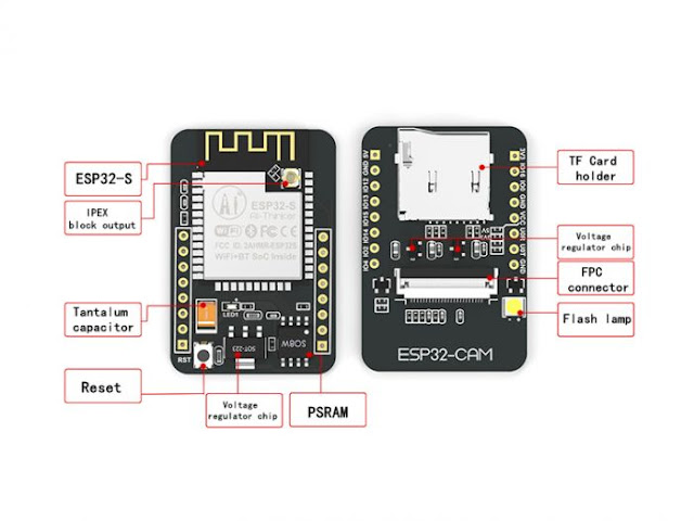
ESP32 Camera
In November 2019 I added a note to a previous blog post that looked at the Arduino project strategy from the angle of a bemused fan regarding a bargain ESP32 board with a camera interface. The delivered price at the time appeared to be £4.95 for the board and £1.99 for the camera. I placed an order in November but I have only now fully opened the package. It turned out that the £4.95 included a camera (OV2640 I think) so I now have a spare. I knew that this board did not have a USB interface so I also ordered a serial to USB board that could run at 3.3 or 5 volts. This cost £2.90. I also took note that the ESP32 chip was known to run hot so I looked out a suitable heat sink.
I ordered the board because it seemed to offer a great deal for the money with 4MB of SRAM, Wi-Fi, Bluetooth and micro SD card slot in addition to the camera port and 512Kb of on chip SRAM. As this could reputedly be programmed in C using the Arduino IDE I was keen to give it a whirl once some other projects were completed. I particularly liked the idea of interacting with it from a web browser following the fun I had with the Arduino MKR WIFI 1010 solving Sudoku puzzles. I also used that same board to develop a skylight closing project featured in the second edition of my Arduino C programming book. That project included a browser based interface that also featured a weather forecast. HTML/JavaScript/CSS interfaces to Arduino based projects look, to me, to be a sound idea.
First step was to add some boards, libraries and sample code to the Arduino IDE. This required using the “Preferences” option from the “File” menu and adding https://dl.espressif.com/dl/package_esp32_index.json to the Additional Boards manager URL list.

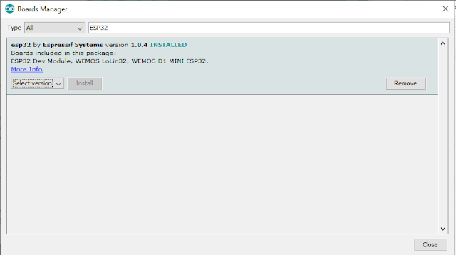
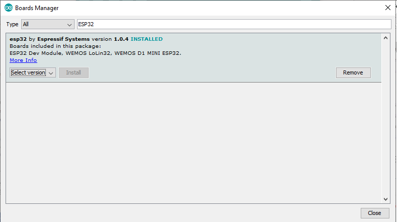
With that in place I went to the “Tools/Board/Board Manager…” option and searched for ESP32. I selected the “esp32 by Expressif Systems” result for installation.
I checked all was well by selecting the newly available “ESP32 Dev Module” board and loading a related example project via the File menu “ESP32/Camera/cameraWebServer”. This project also looked like a good demonstrator for my setup as there looked to be a lot of board and camera options.
I saved the example project to a new folder so that I could make and save changes easily. The first thing I added was a new tab called secret.h (a standard precaution) to hold the SSID and password for my nearest WiFi access point.
const char SECRET_SSID[] = "*****************";
const char SECRET_PASSWORD[] = "************";
Then added a #include for secret.h and referenced the values in the CameraWebServer.ino file.
I was happy to see the line “#include <WiFi.h>” in the example program as I was already familiar with that code base from earlier projects.
I used female to female jumper wires to connect the USB to TTL serial widget to the ESP32 CAM board. When uploading a new program there needs to be a jump wire between the board GPIO 0 pin and Ground. Connecting via a USB cable to my PC saw LEDs on both board light up which was a good start.


I ordered the board because it seemed to offer a great deal for the money with 4MB of SRAM, Wi-Fi, Bluetooth and micro SD card slot in addition to the camera port and 512Kb of on chip SRAM. As this could reputedly be programmed in C using the Arduino IDE I was keen to give it a whirl once some other projects were completed. I particularly liked the idea of interacting with it from a web browser following the fun I had with the Arduino MKR WIFI 1010 solving Sudoku puzzles. I also used that same board to develop a skylight closing project featured in the second edition of my Arduino C programming book. That project included a browser based interface that also featured a weather forecast. HTML/JavaScript/CSS interfaces to Arduino based projects look, to me, to be a sound idea.

First step was to add some boards, libraries and sample code to the Arduino IDE. This required using the “Preferences” option from the “File” menu and adding https://dl.espressif.com/dl/package_esp32_index.json to the Additional Boards manager URL list.

With that in place I went to the “Tools/Board/Board Manager…” option and searched for ESP32. I selected the “esp32 by Expressif Systems” result for installation.
I checked all was well by selecting the newly available “ESP32 Dev Module” board and loading a related example project via the File menu “ESP32/Camera/cameraWebServer”. This project also looked like a good demonstrator for my setup as there looked to be a lot of board and camera options.
I saved the example project to a new folder so that I could make and save changes easily. The first thing I added was a new tab called secret.h (a standard precaution) to hold the SSID and password for my nearest WiFi access point.
const char SECRET_SSID[] = "*****************";
const char SECRET_PASSWORD[] = "************";
Then added a #include for secret.h and referenced the values in the CameraWebServer.ino file.
const char* ssid = SECRET_SSID;
const char* password = SECRET_PASSWORD;
I used female to female jumper wires to connect the USB to TTL serial widget to the ESP32 CAM board. When uploading a new program there needs to be a jump wire between the board GPIO 0 pin and Ground. Connecting via a USB cable to my PC saw LEDs on both board light up which was a good start.

My first attempt at compiling and uploading the test program resulted in an error message from the Arduino IDE to say that the compiled program size exceeded the available board memory. Clearly my random stab at selecting a board type needed to be refined to find one with the correct RAM chip. A little research at the ESP32 board supplier’s web site (one of the illustrations provided the clue and no ,I did not buy it direct from that site) led me to choosing the “AI Thinker ESP32-CAM” board option found way down the list of those available to the Arduino IDE. This helped with the choice of camera so I was able to comment out the default option of CAMERA_MODEL_WROVER_KIT in the program and replace it with:
#define CAMERA_MODEL_AI_THINKER
With the new board and camera selection I was able to upload
the program. I needed to scroll the lower window on the Arduino IDE to see when the upload was complete.

Once the upload had finished then I disconnected the jumper
wire on the board that set the board in flashing mode and then clicked the reset
button on the board. That button is tiny and the action a bit fiddly.
The program executed on the board but seemed to get stuck
when trying to connect to the designated Wi-Fi hotspot. There followed a
lengthy struggle to identify the initial problem and to then get a successful connection.
First off, I wondered if the board’s Wi-Fi module was connected to the external
antenna socket instead of the on board squiggle. A careful inspection with a
magnifying glass persuaded me that it was probable correctly connected to the on
board antenna. Next I wondered if there was a lack of power reaching the board
and so switched to an external power supply. This was easy as the board has 3
ground pins and so there was a spare ready for me to use for the external
supply as well as leaving the others to match ground over the serial link and
to pull the GRIO 0 pin down when uploading a program.
The power change did not seem to help so I wrote a simple program to just list the available SSIDs. This had the benefit that it checked that the Wi-Fi module was functioning.
If you make a change to a program running on this board and need to upload again then first reconnect the jumper wire between GPIO 0 and Ground and then click the reset button to prepare the board for the upload.
What I found was that I had two local Wi-fi hotspots with
identical SSID values (wait, what?). On checking I found that they did not have the same
password so it looked likely that the board had been trying to connect to the “wrong”
one. That should have cleared the issue but the program still failed to
connect. Another simple program to do nothing other than connect to WiFi did
work and I could see the board listed when I ran an IP scanner.
There were minor code differences between my Wi-Fi
connection process and the code in the Example program. I amended the example
program to match my working code. Could have been coincidence but with that
code adjustment the program displayed the same IP address as my connection test
program in the Serial monitor and when I entered http://192.168.0.91 into a
browser tab I was suddenly presented with a web page and a click on a button
rewarded me with a picture of the underside of my chin.

I could now stream video from the module camera over Wi-Fi. Not a bad start even allowing for the connection frustrations.
My connection code block looked like:
  Serial.println("Connecting to WiFi...");
  if (WiFi.status() != WL_CONNECTED) {
      while (WiFi.begin(ssid, password) != WL_CONNECTED) {
        delay(500);
      }
  }

  Serial.println("WiFi connected");
  Serial << "Local IP: http://" << WiFi.localIP() << '\n';
  Serial << "Signal strength: " << WiFi.RSSI() << '\n';
  Serial.flush();

  startCameraServer();

  Serial.println("Camera Ready!");
Although I also added the following Serial snippet before the
setup() function:
template<class T> inline Print &operator<<(Print &obj, T arg) {
  obj.print(arg); return obj;}
Next I want to explore the SD card and to then take a long look at the code supporting the camera to see where I can insert some functions of my own.

Comments
Post a Comment